1. What is IoT
IoT is an advanced function which allows to get information of any things need to be monitored, connected and interacted in real-time via various technologies and devices, like sensor and RFID to smartly realize perceiving, recognizing and managing things.
2. How to set IoT
(1) Model
lIoT 12X H.265+ Mini PTZ Bullet Network Camera
(2) Settings
Step 1: After logging into the web, go to “Advanced Settings”→ “IoT”. Check the checkbox “Enable IoT”, then set the IoT settings as shown below. 
[Channel Plan]: The required Channel Plan can be selected according to the country region.
[Frequency]: Fill in the required frequency.
[Spread Factor]: From SF7 to SF12, the transmission rate decreases and the transmission distance increases. In general, the range of Spread Factor is SF7 ~ SF12, the default value would be SF10. Only the Spread Factor range of the Channel Plan US915 is SF7 ~ SF10, the default value is SF8.
[Bandwidth]: 125KHz, 250KHz and 500KHz are available, the default option is 125KHz.
Note:
The configurations of Channel Plan, Frequency and Spread Factor here should be the same with those in End Device.
Step 2: Configuration of End Device Management. 
[Device Name]: Customize the device name.
[Device EUI]: Fill in Device EUI which can be obtained from the device label. You can also get Device EUI from Milesight Tool Box if you use Milesight Lora Sensor/Lora Sensor Node.
[Device-profile]: Select End Device communication mode and network access mode. The default option is ClassA-OTAA.
[Frame-counter Validation]: This function can be used to judge whether the package loss occurs.
[Application Key]: Only if you choose the OTAA network access mode, you need to fill it in. It is mainly used to generate corresponding Device Address/Network Session Key/Application Session Key. The default value is 5572404c696e6b4c6f52613230313823.
[Device Address]/[Network Session Key]/[Application Session Key]: Information needed to access the network. If you choose ABP network access mode, you need to fill in these items. And you can obtain them from End Device. For example, you can get such information from Milesight Tool Box when you use Milesight Lora Sensor/Lora Sensor Node.
[Uplink Frame-counter]: Calculate the number of uplink frames sent from End Device to network server. This count is increased and received by the End Device. The default value is 0.
[Downlink Frame-counter]: Count the number of downlink frames sent from network server to End Device. This count is increased by the network server. The default value is 0.
[Device Type]: Select the device type according to the actual situation. Lora Sensor and Lora Sensor Node are optional. Lora Sensor is a kind of sensor that supports LoraWAN protocol, while Lora Sensor Node is a kind of device which receives data from interfaces of RS485, AI and GPIO.
[Font Color]: Configure the OSD font color.
[Font Size]: Configure the OSD font size.
Note:
1. Device Name and Device EUI cannot be repeated.
2. Device EUI, Application Key, Device Address, Network Session Key and Application Session Key should be consistent with the configuration of End Device.
3. Uplink Frame-counter and Downlink Frame-counter can be reset only in ABP mode.
Step 3: Sensor Settings. You can enter sensor configuration page by clicking Sensor . After the configuration is finished, you can click Save to save your configuration or click Cancle to cancel your configuration. 

[Sensor ID]: Select the Sensor ID that you want to configure. The number of sensor IDs depends on how many kinds of data the sensor has and there is a one-to-one relationship between ID and data.
[Port Type]: Select the correct port type according to the actual situation. RS485, GPIO and AI are available.
[Channel ID]: Select the Channel ID that you want to configure. There are eight Channel IDs for each kind of interface.
[Osh]: The high value of the device range.
[Osl]: The low value of the device range.
[Sensor Type]: Sensor Type configuration. We have several common used sensor types and you can also customize it.
[Sign]: The tick indicates that the value has a plus or minus sign.
[Decimal Place]: Decimal configuration. For example, when you fill in 1, you are moving the decimal point one to left, and you get a decimal.
[Unit]: Data unit configuration. We have some common units here and users can also customize it.
[Show OSD]: As the picture shown below, once you enable this function, you can see the detected data on the screen. 
Note:
1. Only if your Port Type is AI can you see Osh and Osl options. And Osl must be less than Osh. Fill in the values of Osl and Osh according to equipment parameter information.
2. The channel ID and Sign should be consistent with those in End Device.
3. Decimal Place is set according to the properties of the sensor. For example, you need to set this value to 1 to get the correct temperature when using the Milesight temperature sensor.
Step 4: You can click  to modify the configuration in End Device Management.
Step 5: You can click  to delete the device you added.
(3) Alarm Setting 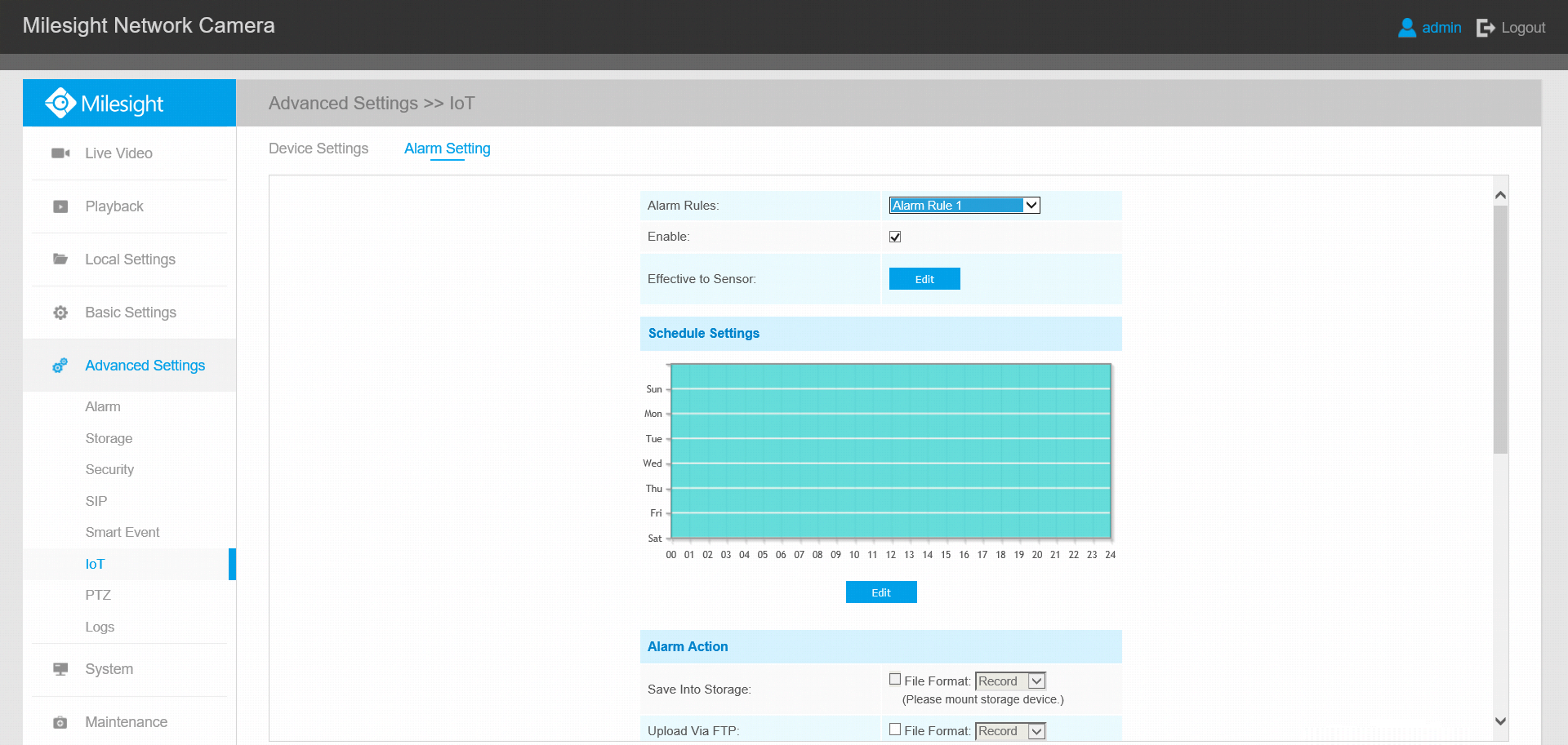
Step 1: Select the alarm rule that you want to set and you can configure four kinds of rules.
Step 2: Check the checkbox to enable Alarm Rules.
Step 3: Click  to select the sensor to alarm.
Step 4: Set threshold for the selected sensor. When the data reaches the critical value, the alarms will be triggered. Both upper and lower thresholds are configurable. You can also only configure upper or lower threshold.
Step 5: Click  to set the alarm schedule for IoT.
Step 6: Set Alarm Action.
[Save Into Storage]: Save alarm recording files into SD Card or NAS.
[Upload Via FTP]: Upload the recording files via FTP.
[Upload Via SMTP]: Upload the files via SMTP.
[External Output]: If the camera equips with External Output, you can enable the action after configuring the trigger duration.
[Alarm to SIP Phone]: Support to call the SIP phone after enabling the SIP function.
[HTTP Notification]: Support to pop up the alarm news to specified HTTP URL.
[White LED]: Support to flash the white LED.
[OSD Blink]: If the Show OSD in the page of sensor configuration is checked, the OSD will blink when alarm is triggered.
Step7: Set alarm settings.
[Record Video Sections]: Six different periods are available (5s, 10s, 15s, 20s, 25s, 30s).
[Snapshot]: The number of snapshot, 1~5.
[Snapshot Interval]: This cannot be edited unless you choose more than 1 Snapshot.
[External Output Action Time]: Length of time that an alarm lasts, this cannot be edited unless you enable the External Output on the Alarm Action firstly.
[White LED Flash Mode]: Always and Twinkle are available.
[White LED Flash Time]: Support to set the flashing duration of the white LED, 1~10 are Available.
[White LED Effective Mode]: Always, Light Environment and Customized are available.
[OSD Blink Time]: Support to set the blinking duration of the OSD, 1~10 are Available.
——————END——————